Butter Bot
A robot gone mad!
A Project By Adeniyi Fagbewesa (amf349)
and Aymen Kabel (ahk86)
15
May, 2023
Demonstration Video
Introduction
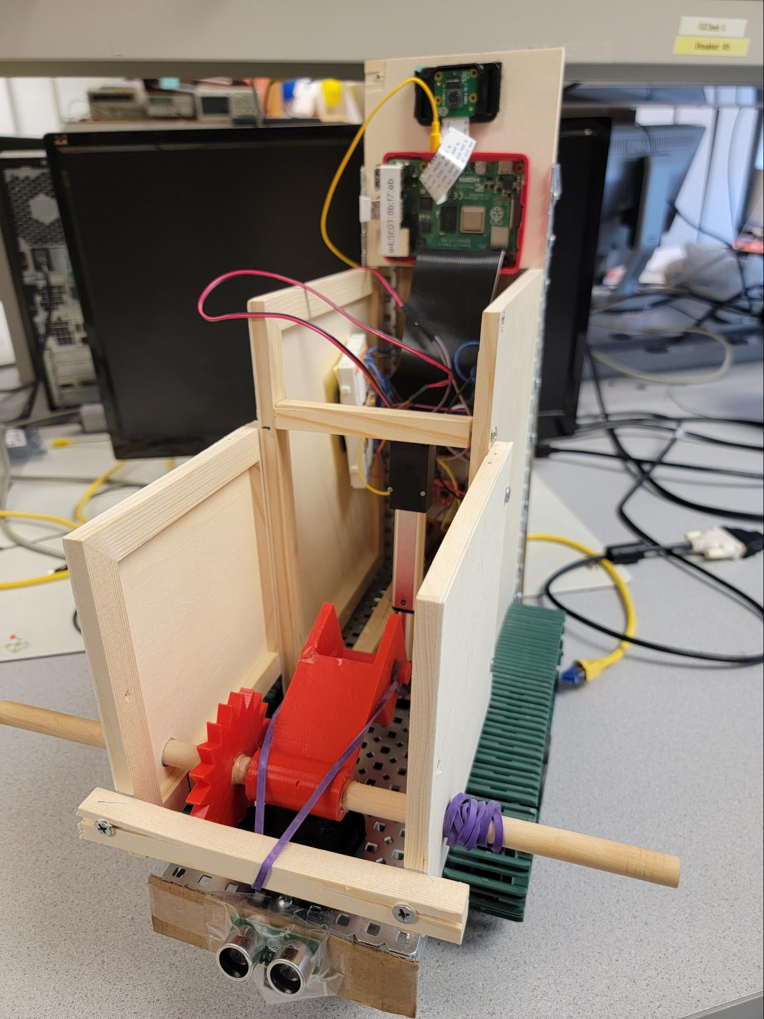
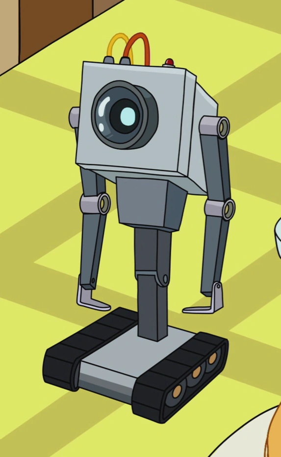
After learning so much about the Raspberry Pi in class, we knew that with it, we would be capable of accomplishing anything we wanted. Of course, the first thing that came to our minds was the Butter Bot from Rick and Morty, as it would be both a complex and fun project to work on. Our version of the Butter Bot is not nearly at the same level as the one in the show, but is still able to accomplish its sole purpose - passing butter. The robot uses a Raspberry Pi camera to detect people in dire need of butter (the first person it finds), then uses a pair of tank treads to navigate towards them. From there, it uses a linear actuator with a razor at the end to cut a piece of butter from a stick loaded inside of it, then launches it at the person using a motorized catapult system. The robot then reloads another piece of butter by winding the catapult back and using another linear actuator to push the rest of the stick inside. It then seeks out its next victim - er, patron - and repeats the process.
Project Objectives:
- Replicate, to the best of our ability, the “Butter Bot” from the hit TV show Rick and Morty
- Include mechanisms to locate and navigate towards people
- Solve the problem of automating the delivery of butter at a dinner table
- Finally, our end goal is to autonomously cut butter and and throw it at people
Design and Testing
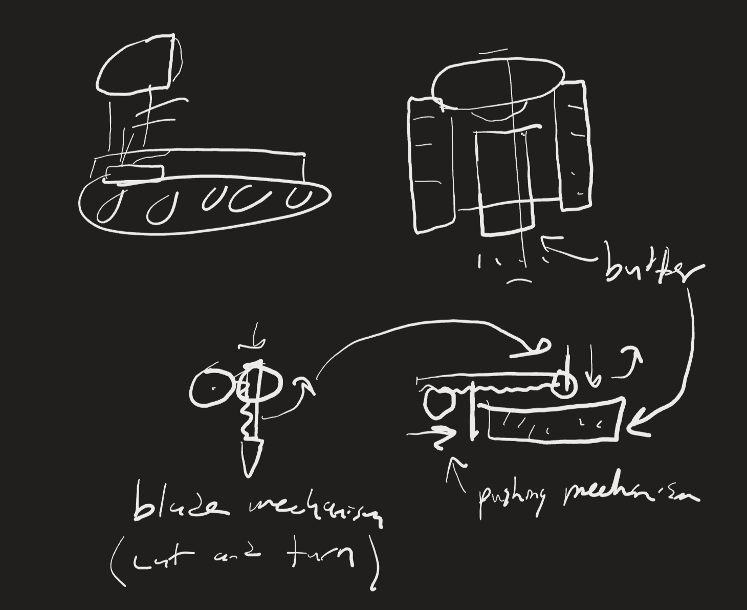
Figure 1: Initial Design of Butter Bot
Movement - We knew we wanted to use tank treads from the start of this project, as they are also what the Butter Bot from the show used. We were fortunate enough to find an entire tank base in Professor Skovira’s lab - the remnants of a previous ECE 5725 project. The tank base consisted of VEX robotics parts and motors, and we ended up using the entire base almost as is. We first resized the base to be more in line with the size we wanted, which was relatively simple to accomplish. The initial tank base had two halves that were joined together underneath to avoid overlap between the two top plates, as well as to give a good distance between two motors, as they were both driving what we believed to be the front wheels. What we did instead was disassemble the connection in the middle and overlap the two plates to decrease the width of the robot. We then redesigned the tank tread system to decrease the length as well. The original design had two sprockets to drive the treads and two brackets with wheels to align the treading in between. For our design, we only used one bracket in the middle and removed some links in the tank treads to account for the slack created as a result. We then had to deal with the problem of having room for only one motor on the “front” of the base. By reducing the width of the base, the initial motor positions were at odds with each other, so we decided to move one of the motors to the “back” of the robot, giving us linear placement of the motors down the center of the base.
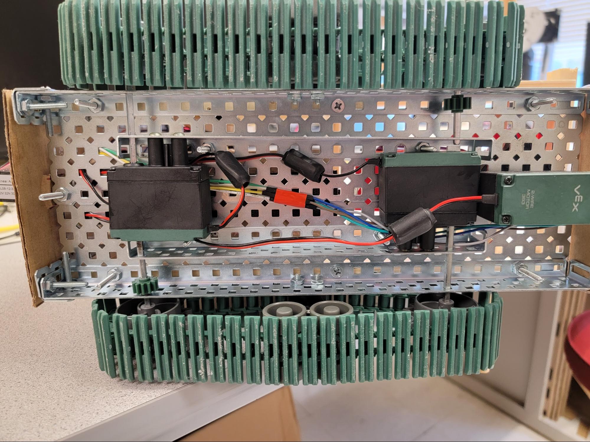
Figure 2: Two drive motors mounted in series. A third motor controlling the catapult system is also shown.
The motors are controlled by a single motor controller connected to the Raspberry Pi. The controller has two main sets of motor outputs, A and B, with each motor connected to one output, and each output requires a PWM signal from the Pi’s GPIO pins that controls the speed and 2 more digital signals to control the direction that the motor rotates. The controller also has two voltage inputs - one for logic and one that is actually sent to the motors. The logic voltage input is connected to the Pi’s 3.3V output pin, and the motor voltage is connected to four AA batteries that provide 6V. We found that the motors were designed to run at 12V, but after conducting several tests with them we concluded that 6V was sufficient for our purposes.
To drive the motors with python, we utilized the gpiozero library to make a Motor class that uses 1 PWMOutputDevice (for the speed) and 2 DigitalOutputDevice (for the directions). At this point, we were able to complete small unit tests to ensure that the motors and motor controllers interface correctly by making the robot move forward, backwards, turn clockwise, and turn counterclockwise. We needed some way to know when the robot should stop moving as well, so we installed ultrasonic sensors to the front of our robot. Luckily, gpiozero had an interface for ultrasonic sensors called DistanceSensor. We could connect functions to fire the instant the ultrasonic sensor measures a distance lower than a defined threshold. From there, we could tell the motors to stop moving since the destination was reached. Again, this was easily tested with a small unit testing file that moved the robot forward until it was 30 centimeters away from an object.
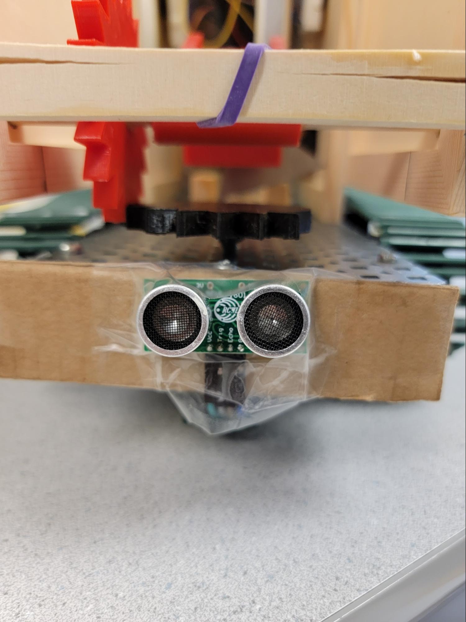
Figure 3: Ultrasonic sensor at the front of Butter Bot
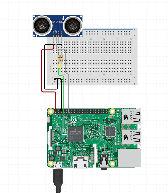
Figure 4: Ultrasonic Sensor Circuit Diagram
Face Detection - An important aspect of our robot’s navigation is knowing where to navigate to. We opted to do this through face detection! This required us to mount our pi camera on top of the robot. The camera had to be as aligned as possible to the center of the robot, for reasons detailed below.
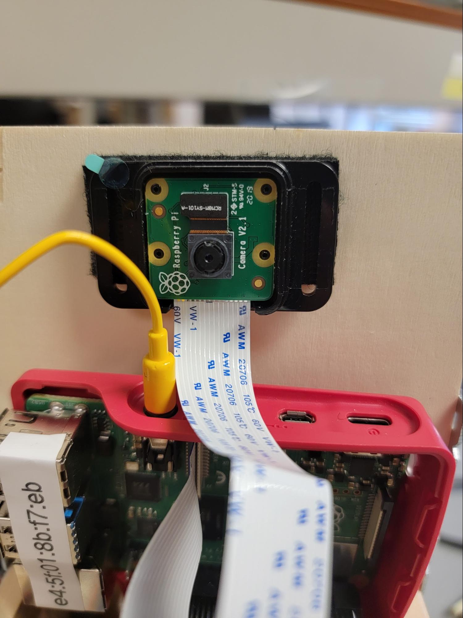
Figure 5: Camera mount on top of Butter Bot
Initially, we had planned to run a more complicated object detection algorithm. One that could detect many different kinds of objects through pre-trained machine learning models like TensorFlow. However, figuring out which model to use with which version of pi, raspbian kernel, python version etc, was troublesome, so we opted for a more lightweight face-detection algorithm that we found online. The one we found uses a defined neural network on OpenCV2 to run a pretrained model for facial detection. These pretrained models are defined in the cmodel.caffemodel and deploy.prototxt.txt files in /Detection/. It works by routing the camera output stream to the openCV neural network. From there, it runs the detection algorithm and reports back with any faces that were detected over a certain confidence.
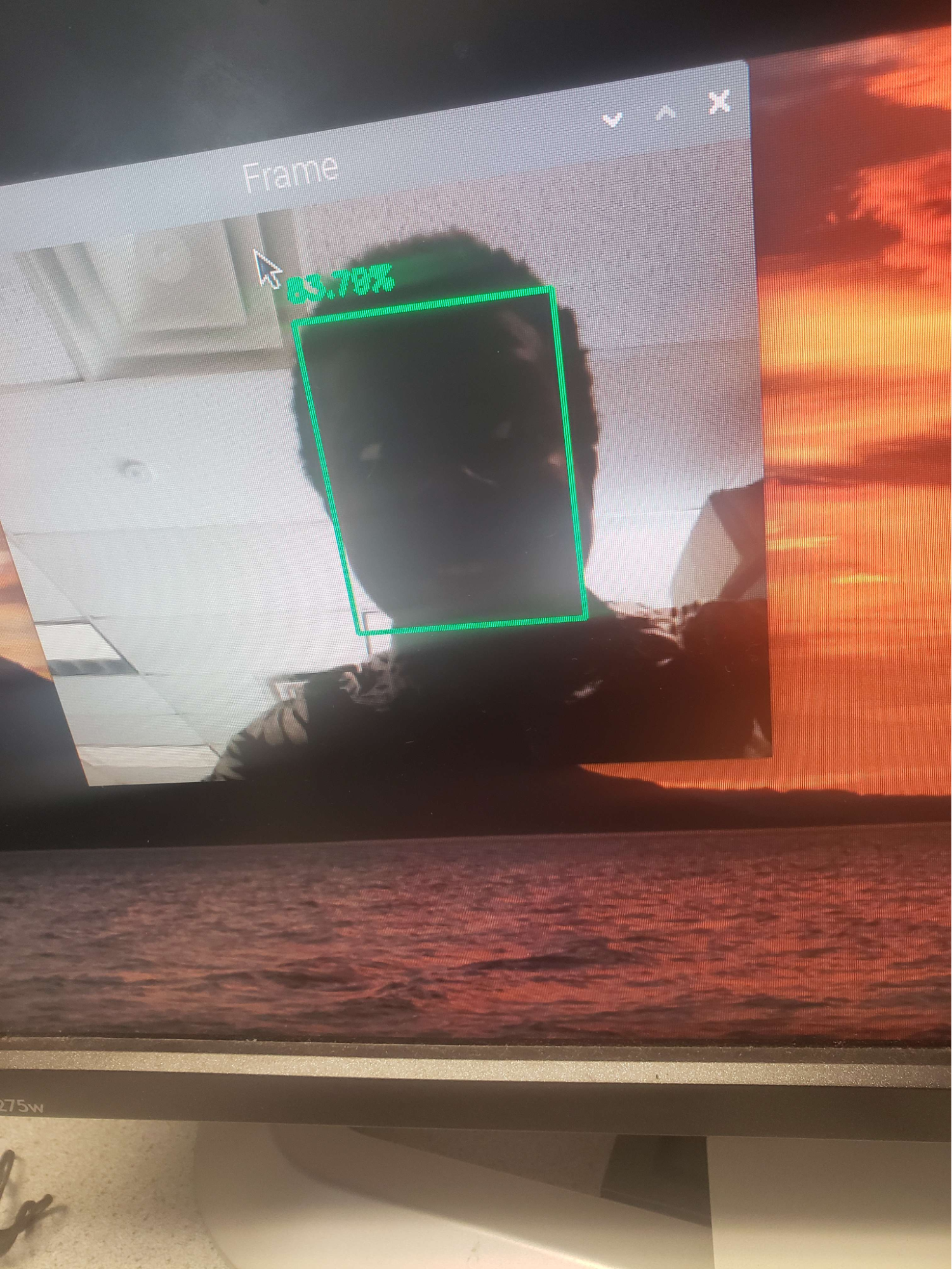
Figure 6: Facial Recognition using OpenCV
As seen in the image above, the confidence that it detected a face was about 84%. Whenever it detects a face, it will return a hull box of the region of the screen that has a face on it. We decided to use this information to handle turning the Butter Bot. For example, if the center of the detected square box was unaligned from center, the bot would stop and immediately rotate to center towards the detected individual. For example, in the figure below, there is a +x offset from the center of the face to the center of the screen. If x is greater than our defined threshold, then we rotate the robot. We turned right for positive offsets and turned left for negative offsets.
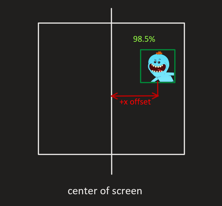
Figure 7: Robot-centering logic diagram
When we tested this mechanism, we ran into the problem of the Butter Bot not knowing who to pass butter to when there were multiple faces on the screen. This led to it constantly rotating between two people sporadically. To resolve this, we took the area of each of the hull squares and obtained the biggest one. The biggest one (ideally), would be the person that is closest to the robot at any given time. For example, in the figure below, the face on the bottom right would be prioritized because its on-screen area is larger than the other face.
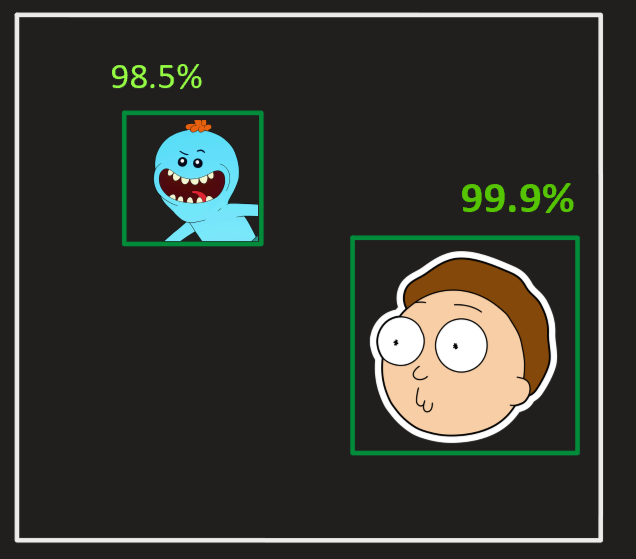
Figure 8: Robot person-selection process
Butter Delivery - This is the bread and butter (pun intended) of our design; our butter delivery mechanism is a fully automated system designed for cutting and shooting pieces of butter at people. We went through a number of different ideas for the delivery system, but ended on one that we felt was straightforward, but still fun.
The first step of our butter delivery system is the pushing mechanism. On startup, the robot is loaded with a full stick of butter, but the rest of the system can only deliver small pieces at a time. To solve this, the robot uses a linear actuator to push the stick of butter down a guided path, lining the next piece up with the rest of the system. For guiding the butter, we used two rails screwed onto a platform, with the width between them being the same as the butter’s width. We also covered the rail system in non-stick material to keep the butter from getting stuck while being pushed.
The second step of this system is cutting the piece of butter the robot will shoot. We use another shorter linear actuator to accomplish this, this time with a blade screwed on to the end. The actuator is mounted to a wood bar running across the width of the robot frame, high enough to be completely extended with the blade attached. The mechanism itself is straightforward; when the robot needs to cut a piece of butter, it will completely extend and retract the blade. Since butter isn’t that difficult to cut, we didn’t need to make any adjustments on the speed of the actuator.
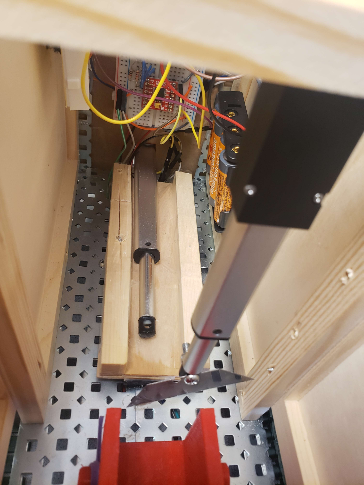
Figure 9: Linear Actuators for Pushing Butter and Cutting Butter
Lastly, the robot needs to actually “serve” the butter it cut to someone. For this part, we got a little creative and designed a catapult mechanism that could function with only a motor driving it. The mechanism consists of a motor mounted underneath the base of the robot, two gears - one fully toothed and the other partially toothed, a catapult arm, rubber bands, and the frame. Both the two gears and the catapult arm were 3D-printed using printers available to us in the Makerspace. Due to the limited availability of VEX components when building our robot, we needed to print the partially toothed gear with a square axle that would connect to the motor. We did our best to design this axle to be as sturdy as possible when undergoing stress while turning, and while we ran into some issues during testing, we found the material was just strong enough to work.
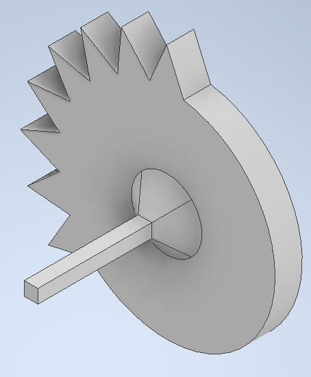
Figure 10: CAD Model of Partially Toothed Gear
The motor that drives the entire catapult system is mounted underneath the base of the robot, with holes lined up to screw it in and attach an axle to it. The partially toothed gear and axle are connected to this motor, which is how the catapult is able to autonomously wind up and shoot. The fully toothed gear and catapult arm are glued to a circular wooden rod that is held up by the frame. A big part of mounting this section of the mechanism was lining up the two gears such that they were able to mesh properly, as we were attempting to mesh them at a 90 degree angle. This required a lot of testing with the motor functions and readjusting the catapult rod, as well as calculating the proper height for the holes on the frame that the rod sits in. Finally, we used a square rod across the robot frame to stop the catapult arm after it shoots and to attach a rubber band to the arm. The rubber band supplies the elastic force needed to propel the arm forward and launch the robot’s butter. After testing, we also found that it was a source of opposing force on the motor when winding up the mechanism, so we resolved this by decreasing the motor’s speed to create more torque.
As for the entire mechanism itself, the catapult begins already wound up, as part of the loaded butter will already be sitting inside it. To wind up the catapult, the arm needs to first be resting on the square rod mentioned before. This is to ensure that when winding up, the arm ends up in the right position to receive butter from the loading stage, as the amount of the partially toothed gear that is toothed dictates how much it needs to rotate. When the toothed portion of this gear meshes with the rest of the mechanism, it will draw the arm backwards and pull on the rubber band, preparing it to launch. A piece of butter is then loaded into the arm, and once the motor starts to spin again it will reach the non-toothed section, releasing the arm gear and launching the butter! The motor can then spin the partially toothed gear back to the loading position and prepare the arm to fire again, thus allowing the robot to complete an entire launch and load motion with one full rotation.
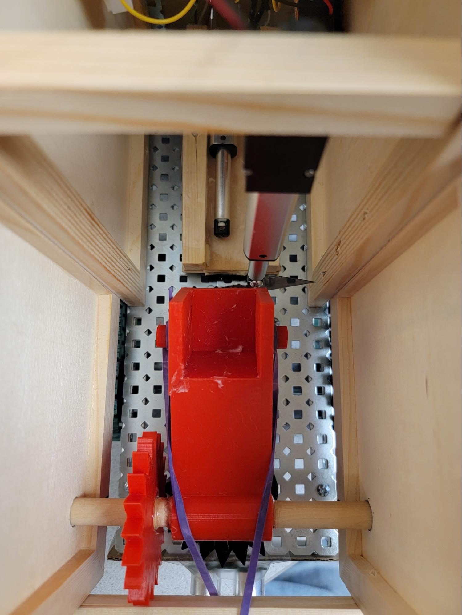
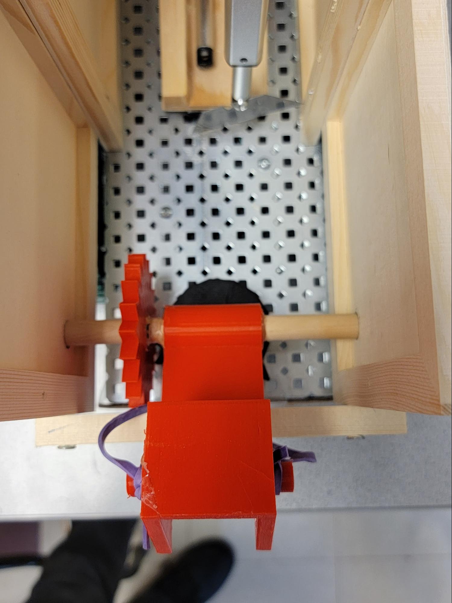
Figure 11: Catapult launch mechanism (Before and After)
The linear actuators we used had the exact same interface as the motors, so our first instinct was to use 1 motor controller to interface both linear actuators. We ran into a problem immediately: there weren’t enough PWM pins on the raspberry pi. The Pi only offers 4 hardware PWM output GPIO pins, but we needed 5 in total. To resolve this problem, we decided to use digital pins for the PWM input for the linear actuator motor controller. This would prevent us from having various speeds, but we decided that it was unnecessary for the linear actuators. All we needed was forward (full speed), backwards (full speed), and stop. Our software implementation had to vary slightly as well. Instead of interfacing the actuators the same as with motors, we needed 3 DigitalOutputDevice instances from gpiozero. We decided to leave the 3 actual motors with PWM signals because they definitely needed to have varying speeds for precision with movement and with launching the butter.
Because we were using one of the VEX motors included with the tank base and not a stepper motor, we needed to rely on timing to fully rotate the gear. Rigorous testing was required to get the right timing, as even a hundredth of a second would make the difference between launching and loading the catapult. However we were eventually able to find a sweet spot for the timing and achieve exactly the behavior we wanted.
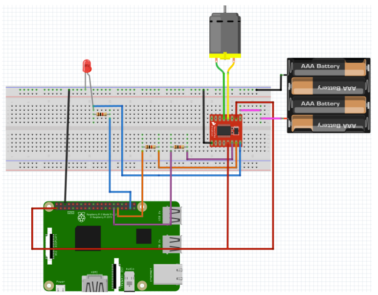
Figure 12: Circuit Diagram - Example Connection of Motor and Controller
Pin Allocation
                # Motor A, Left Side GPIO CONSTANTS
                PWM_DRIVE_LEFT = 13		 # ENA - H-Bridge enable pin
                FORWARD_LEFT_PIN = 5   # IN1 - Forward Drive
                REVERSE_LEFT_PIN = 22	 # IN2 - Reverse Drive

                # Motor B, Right Side GPIO CONSTANTS
                PWM_DRIVE_RIGHT = 19		# ENB - H-Bridge enable pin
                FORWARD_RIGHT_PIN = 6	# IN1 - Forward Drive
                REVERSE_RIGHT_PIN = 26	# IN2 - Reverse Drive

                # Motor C, Catapult GPIO CONSTANTS
                PWM_DRIVE_CATAPULT = 18		# ENB - H-Bridge enable pin
                FORWARD_CATAPULT_PIN = 14	# IN1 - Forward Drive
                REVERSE_CATAPULT_PIN = 15	# IN2 - Reverse Drive

                # Push Actuator GPIO CONSTANTS
                PWM_DRIVE_PUSH = 25 		# ENB - H-Bridge enable pin
                FORWARD_PUSH_PIN = 24 	# IN1 - Forward Drive
                REVERSE_PUSH_PIN = 23 	# IN2 - Reverse Drive

                # Blade Actuator GPIO CONSTANTS
                PWM_DRIVE_BLADE = 12		# ENB - H-Bridge enable pin
                FORWARD_BLADE_PIN = 20	# IN1 - Forward Drive
                REVERSE_BLADE_PIN = 16	# IN2 - Reverse Drive

                US_PIN_ECHO = 21
                US_PIN_TRIG = 7
Result
Overall, everything worked as planned. We reached our goal of autonomous driving, facial detection, navigation, butter cutting, and throwing. We had planned to make the concept of butter delivery as close to the spirit of the show as possible as well as autonomous, so we achieved our project goals to that end. Even though we had slight changes to our plans, our end result was still within the confines of our initial goal.
Conclusion and Future work
To conclude, we had a fun time working on this project. Bringing a wacky idea from a TV show to life was an arduous challenge, but worth it. What better use of embedded systems than to complicate a simple, easy task like cutting butter into a complicated autonomous one? We faced many challenges along the way while constructing our robot. For example, the bot looks a lot larger than what it looks like in the show. This was a necessary extension if we were going to be able to freely experiment with different features of our bot without forsaking the structural integrity. Now that things are definitely working, however, making a more compact bot would definitely be ideal for future iterations. Our catapult system has seen many iterations because our initial designs simply wouldn't work. After some long thinking, however, we were able to reach an optimal design that properly throws butter. This project was really fun to work on!
There are various avenues for future work on this project. For one, we could maintain consistent accuracy by using a stepper motor for the catapult instead of a continuous servo motor. This would remove the need to calibrate our Butter Bot before each run, making things easier to test and easier to use! A secondary thing we could do is preload our robot with multiple sticks of butter and have the robot autonomously restock the butter whenever it runs out. The purpose of this would be to remove the need to manually reload the stick of butter every time a single stick is done. This would then lead to long-term storage of butter, which suggests refrigeration (and making our hardware components cold-proof). We also had the idea of doing voice activation for our robot, so one could tell it when to engage and disengage. Finally, we could have downwards-pointing sensors that would prevent the Butter Bot from accidentally driving off the edge. This would limit its driving to the confines of a dinner table without external guidance, making our design even more autonomous.
Work Distribution
Project group picture
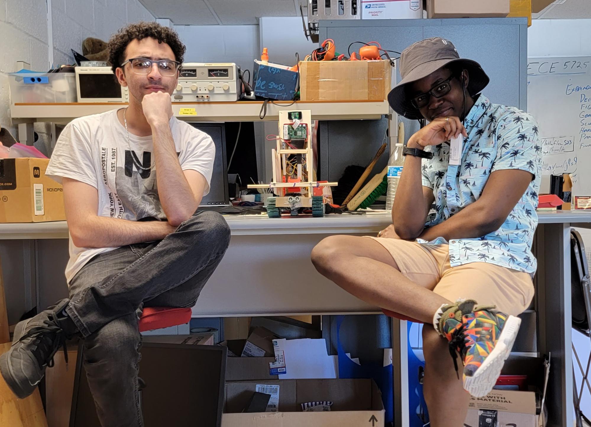
Aymen (left) and Adeniyi (not left)
Aymen
ahk86@cornell.edu
Designed 3D printed parts
Designed/built bot structure, including catapult
Overlooked the hardware integration
Testing
Adeniyi
amf349@cornell.edu
Integrated facial detection software
Created the software control flow
Wired hardware components together
Testing
Parts List
- Raspberry Pi - Provided in lab
- Raspberry Pi Camera V2 - Provided in lab
- Tank Tread Base (metal, motors, wheels, axles, screws, nuts) - Provided in lab
- Resistors, Breadboards, Velcro and Wires - Provided in lab
- JBL Speaker - Provided in lab
- 3D Printed Parts - Provided in lab
- Motor Controllers x3 - Provided in lab
- Wood Frame x5 - $10
- Wood Rod (Circular) - $2
- Wood Rod (Square) x2 - $3.50
- Rubber Bands x3 - $0.27
- 2in Linear Actuator - $33
- 4in Linear Actuator - $22
- Portable Charger - $21
- 4x AA Batteries and Holder - $3.75
- Blade - $0.50
Total: $96.02
References
Rick and MortyPiCamera Document
Motor Controller Datasheet
Bootstrap
Face detection with openCV
Gpiozero Library
OpenCV2